Orthotropic Weighbridge
Customized orthotropic beams designed precisely for the purpose of truck scale application. These orthotropic beams are a global norm today and world-leaders are aggressively using these designs across Europe and America. The only reason that such a design is reaching late to Indian customers is that, it requires precise designing tools and a very large upfront investment in the form of state of art machinery. Being a company committed to providing value to our Esteem Customers, we have invested in state of art machinery to bring the best (in weighbridge structures) to you.
The Design of Orthotropic Weighbridge:
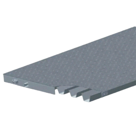
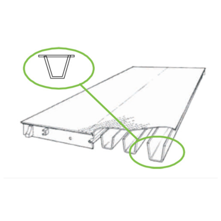
Orthotropic is a fancy word for a structure that's strong in different ways depending on which direction you're looking at it from. Imagine a bridge where it's super tough to drive over it, but not as much if you try to push down on it from the side. There are different designs for this kind of bridge, and the one DIGI WEIGH uses has a deck held up by strong, closed ribs that look like trapezoids. It's a design that's been used in big projects like rebuilding the Golden Gate Bridge and fixing up Germany after the war. But why isn't it everywhere? Well, it's expensive. Making this kind of bridge costs a lot of money upfront, and not everyone wants to spend that much to make sure their bridge is super sturdy.
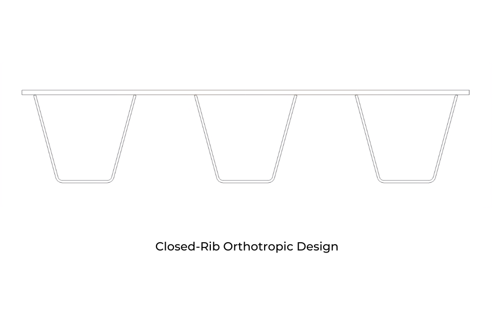
There are different ways to design an orthotropic bridge section, but the closed-rib design stands out as one of the strongest and most efficient options. Unlike the sandwich design, which combines plates and beams, the closed-rib design is made up of individual ribs. This distinction is important because the closed-rib design offers superior structural efficiency.
In the closed-rib design, a truck's weight is concentrated at the load points where its tires touch the bridge's surface. To handle this concentrated load effectively, the bridge should distribute it across multiple ribs adjacent to each load point. Because the closed-rib design excels at spreading the load, it proves to be stronger and more efficient.
When a load is directly over one of the ribs, each design reacts differently. In the open-rib design, the I-beams next to the load point bend, resulting in less support. However, in the closed-rib design, the torsional rigidity of the ribs resists deformation, allowing adjacent ribs to provide substantial support and ensuring more even distribution of the load.
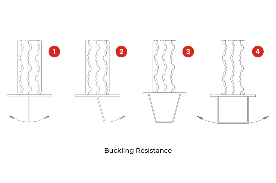
In the closed-rib design, another advantage is its resistance to buckling. When we look at Figure 1, which displays an open rib directly beneath the load, we see that the beam's web can buckle to the right or left, leading to rib failure. To prevent buckling, additional stiffeners would be necessary. Now, if we examine Figure 2, we observe one leg of a closed rib and its inherent tendency to buckle. In Figure 3, a closed rib with a trapezoidal design is depicted. Since each leg tends to buckle inward, the opposing forces counteract each other. Moreover, the flat section between the legs facilitates load transfer, preventing buckling. Consider a scenario where the closed rib is square, as shown in Figure 4. Similar to the I-beam design, the legs could buckle in either direction. However, the flat bottom of the rib is less effective, as both legs could fail in the same direction, potentially leading to rib collapse.
Challenges in Analyzing the Strength of Orthotropic Bridge Structures
Analyzing the true strength of an orthotropic bridge structure poses considerable challenges. The calculated strength often underestimates the actual strength by a significant margin. For instance, tests conducted on the open-rib design revealed that its actual strength is 10.3 times greater than the calculated strength. However, testing for the closed-rib design could not be finalized as the test equipment failed when the load reached 42 times the calculated strength.
The structure incorporates epoxy based paint technology with dual paint coats to give a superior finish and long life to the structure to give excellent results in the long run. This is very different from cheap black bituminous paint coated on the run of mill truck scalesmanufactured in India. Although a little expensive, this paint compensates for its long life and outstanding performance.
The structure is a machine for vehicle weighment and not a bundle of steel beams and plates made by any local fabricator without the basic knowledgeof weighing technology. Having invested time, effort and money in designing superior structures with precise designing using latest CAD and CAE procedures, we are committed to deliver a machine, not just steel.
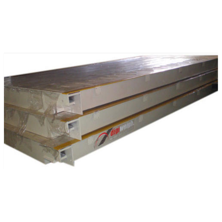
Tested and analyzed using actual industrial loads to ensure a robust product. Heavy duty fabrication using branded high UTS steel. Non Destructive Test methods used to test the strength of EACH fabricated structure in actual loaded condition.
All of our steel deck designs are supported by orthotropic ribs with fully automated, continuous welds. Every rib is pressure tested to ensure an airtight seal that eliminates the potential for rusting.
Resistance to Metal Fatigue in Closed-Rib Design
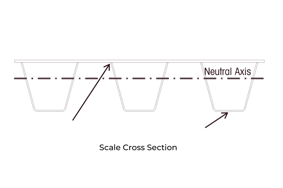
The closed-rib design offers enhanced resistance to metal fatigue due to strategic placement of welds away from high-stress areas of the bridge. These welds are positioned as close as possible to the neutral axis, a critical concept in bridge mechanics.
The neutral axis refers to the point within a bridge structure where stress is neither compressive nor tensile. As a vehicle drives onto a scale module, the module experiences bending, with its top surface compressed and its bottom surface under tension. Moving downward from the top surface, compression decreases, while moving upward from the bottom surface, tension decreases. The neutral axis is where stress is zero.
In the closed-rib design, the neutral axis is closer to the top surface of the deck. This means that stress is highest at the bottom of the rib, farthest from the neutral axis. By locating welds in the lower stress region where the ribs meet the underside of the deck plate, near the axis and away from the bottom of the rib, the design minimizes the risk of metal fatigue.
The design also reduces metal fatigue by using continuous welds to join the rib to the deck plate. A start or stop in a weld increases local stresses and the potential for failure. For this reason, we do not use intermittent welds.
The closed-rib design plays a vital role in prolonging the scale's lifespan by minimizing the risk of internal corrosion. Every rib is hermetically sealed to restrict moisture ingress within the rib enclosure. Once the minimal moisture trapped inside the rib undergoes a reaction with the metal to produce iron oxide (rust), the rusting process halts. With no further moisture infiltration into the chamber, the scale is safeguarded against internal rust formation.
DIGI WEIGH has dedicated significant resources to create and produce the leading weighbridge for vehicle scales in the industry. Should you have any inquiries regarding our weighbridges or require further clarification on any details provided in this datasheet, please feel free to reach out to us.
Highlights of Weighbridge Structures with Orthotropic Sections:
-
The structures are manufactured by using closed orthotropic sections Q beams. These sections are completely welded with the top plate and side plates. This makes the structure very stiff and load distribution is even because of closed section geometry. When there is concentrated loading on the structure there is no deflection and the load transfer is always vertical on the Load cells. This results in high accuracy in weighment.
-
There is no chance of structure buckling, even on large loads, as these are closed sections. The FOS (Factor Of Safety) of the structures is consistently maintained to be greater than 1.4.
-
In these sections the point of maximum stress is away from the welded / bolted points.
-
The Orthotropic sections are manufactured by using Grade specific Plates, which are manufactured only by certified companies like SAIL Essar, Jindal, Ispat etc. Compared to the beams available in market which are re-rolled by many manufacturers. The thickness of the flange of re-rolled I beam may vary by +/- 20% from point to point, if it is not from a branded supplier. This leads to lower structural strength from the design specifications.
-
In bolted I Beam Structures, the strength of bolts becomes very critical and sometimes leads to failure, if the bolts used are not proper or in lesser quantity. The structures using orthotropic sections are completely welded using high quality welding equipment. Thus the possibility of structural failure is minimal as there are no bolted joints.
-
These structures are designed by using latest CAD tools and structural analysis software. These structures are also tested by using actual weights in the factory premises.
-
The structures are of considerably lower height compared to I beam based structures. This reduces the cost of civil construction, as the ramp size is reduced.
-
High quality paint is used for long time protection of steel from corrosion.
-
Very easy to install.
-
Major manufacturers of Weighbridges world over like Mettler Toledo and others, use closed orthotropic section based designs, as these are capable of handling more load and are more rugged compared to I beam based structures. However, due to lack of production facilities in India, they are unable to offer these structures and instead promote I beam type of structures.
-
The concept of selling I beam based structures is more focused on the quantum of steel and lesser on the actual design of load bearing. The concept of closed orthotropic sections based structure is focused on the actual loading and weighing functions and generating more accuracy in weighing.
Load Cell
Load cells play a crucial role in orthotropic weighbridges, ensuring accurate weight measurement. These specialized weighbridge designs utilize load cells strategically placed at key points to detect and transmit the weight of the vehicle to the weighing system.
The load cells in orthotropic weighbridges are typically mounted beneath the surface of the bridge deck, often at the ends of the closed ribs or at other predetermined locations. This placement allows them to efficiently sense the load applied by vehicles passing over the bridge.
Explore Range
Indicators
Our smart indicator panels, available in both analog and digital ranges, revolutionize weighing operations with advanced technology and user-friendly interfaces. With precise measurement capabilities and intuitive controls, our analog models offer traditional reliability, while our digital panels boast cutting-edge features for enhanced accuracy and efficiency. Designed for diverse applications, these panels streamline weighbridge operations, ensuring seamless integration and optimal performance across various industries.
Explore Range
Softwares
Our weighbridge software is designed to take the load of your weigh ment with the help of unmanned weighbridges, weighbridgec alibration procedure,weighbridge specification, and weighbridge automation facility. We stand with you from initiating to implementing an absolute weighing innovationto provide you with a single way out for each ofyour weighing requirements.
Technical Specifications:
| Specification | Available Range |
|---|---|
| Size | 8 Mtr To 24 Mtr |
| Capacity | 10 Ton To 150 Ton |
| Pit Design | Pit Type Pit Less |
| Indicator Designs | Intelligent Terminals |
| Indicator Type | Digital Analog |
| Loadcell Designs | Ball Type Compression |
| Loadcell Type | Digital Analog |